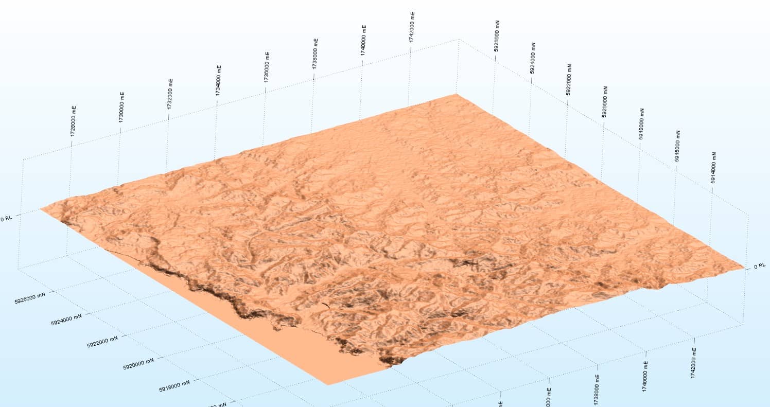
Wireframes are one of the most powerful tools in a 3D environment. For example, they can be used to represent geological models, topography, ore bodies, grades shells, pit designs and underground workings.
Almost everyone will have a view that includes a topographic wireframe (or DTM).
 |
 |
|---|
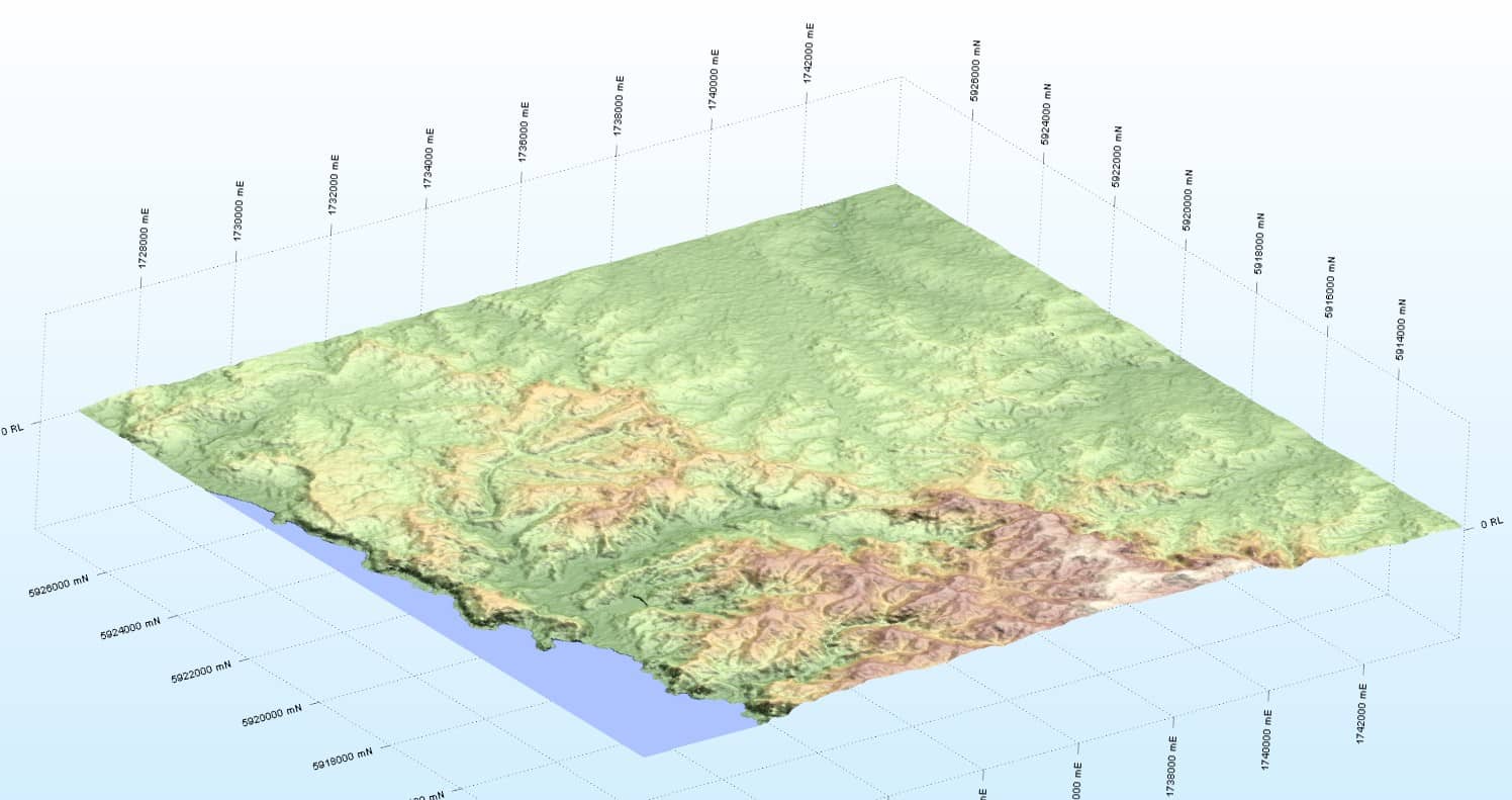
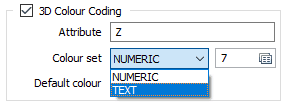
The ability to colour code the triangulation, based on elevation, adds to the visual impact. The colour coding is based on a wireframe attribute. Unlike a field in a Micromine data file, attributes are undefined in terms of whether the content should be treated as Numeric or Text. This requires user input and, in 2018, the attribute classification has been clarified.
What was less clear, prior to 2018, is how the display would look if you chose 2D Slice mode in a sectional view. The thickness and colour of the resultant profile line (in the case of a DTM) was controlled by the hatch pattern patch, alongside the 2D Slice radio button (unless it was the NUL pattern!).
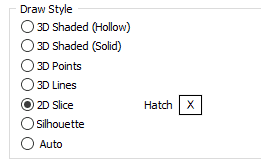
It was unintuitive to have the style of the profile line, associated with the border of a hatch pattern. The complication is that the 2D Slice for a simple surface is a line and for a solid it is a polygon. In the second case (solid) a hatch pattern is entirely appropriate, and it is difficult to separate the two cases.
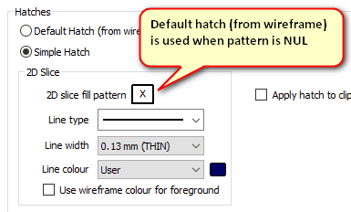
In 2018 there are now three hatch options. It is expected that most users will opt for the Simple variant, where the parameters look like this.
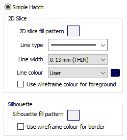
The 2D Slice line style parameters have been brought to the top level. Indeed, when you open the 2D slice fill pattern, the border options are blanked out. The line type, width and colour can now be seen on the main form and apply to the profile (for a simple surface) and to the hatch border (for a solid). When applying a fill pattern, there is an option to use the wireframe colour as the foreground colour. This was previously not possible.
Another significant improvement is the additional control over the line type and width (previously the options were Thin, Medium, Thick, Dot, Dash).
Note: A Silhouette differs from a 2D Slice because it is always a polygon. This means that the profile line options are unnecessary for a Silhouette.
There are two other hatch options: Advanced and Default.
- Advanced: This will mainly be used when the input is a wireframe set. The 2D Slice and Silhouette buttons open sub-forms with the provision to control all hatch properties using Line, Colour and Hatch sets that are based on wireframe attributes.
- Default: 2D Slice and Silhouette hatch patterns can be saved to the wireframe itself and these values will be used when the default option is chosen. The initial settings for 2D Slice and Silhouette will be no fill with a border line width of 0.35mm, drawn using the wireframe colour. The 2D Slice line type is solid while the Silhouette is dashed.
Note: When the display option is Simple hatch, then the default pattern can still be used by setting the fill pattern to NUL (this is done by pressing the DEL key when the patch has focus).
Although I said that I think most users will opt for the Simple hatch option, the default method is worth considering. Let’s look at how you can update the wireframe hatch properties.
- Use the Wireframe | Manage | Change Hatch function. This replicates the parameters of the Advanced option in the Display form but writes the results to the wireframe.
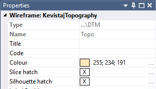
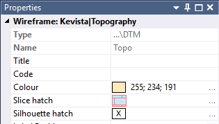
- Display the wireframe in Vizex. Then select it and open the Property Pane.
 |
 |
|---|
The left screenshot shows the initial state (NUL hatch). If the hatch has been defined the pattern will be shown (Slice hatch – right screenshot). In either case clicking on the ellipsis (or double clicking on the pattern) will open the Fill Pattern editor.
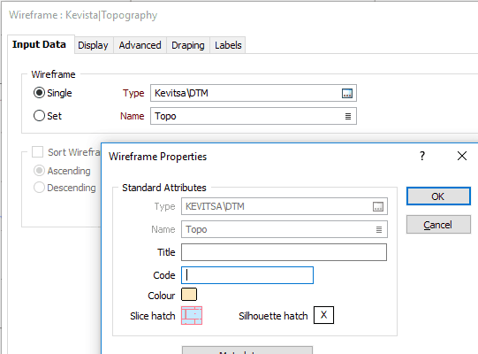
- From the Wireframe Properties dialog. The most convenient way to open this is to right click on the wireframe Name response field in any form.
Double click on either the Slice or Silhouette “patch” to edit the hatch pattern. If you want to revert to the NUL hatch, click on the patch and press the DEL key (this is not supported in the Property Pane).
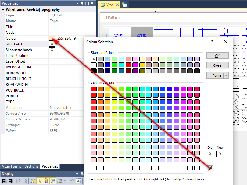
Here is a handy tip, that you can use anytime you want to make a new colour selection match a colour that you already using. Let’s say that are editing the Slice hatch for a wireframe, and you want the foreground colour to be the same as the wireframe colour.
Select the wireframe and open the Property Pane. Now edit the hatch by double clicking on the patch. Double click on the foreground colour. Note how the Colour Selection dialog has an eye dropper tool in the bottom right corner. Drag this until it is over the wireframe colour patch in the Property Pane. Release the mouse button and click OK.
Apply Hatch to Clipping Planes: If the draw style is 3D Shaded (Solid and Hollow), and the 2D Slice Hatch is selected, then that border line style and pattern (no fill for Hollow) and will be used to draw the end cap(s) in Single Clipping Plane mode or in Clipped view.
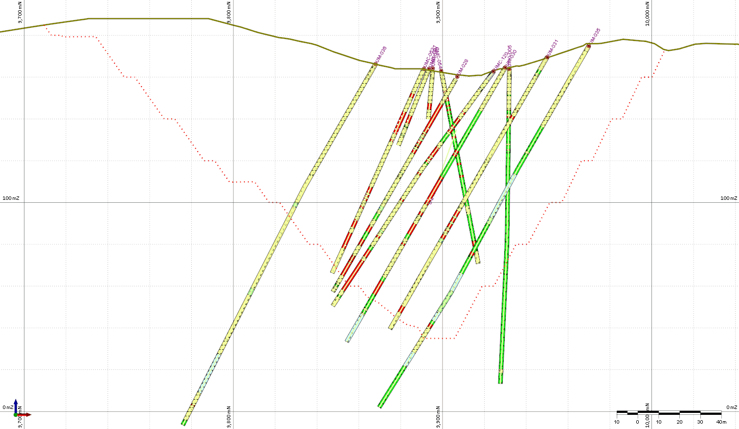
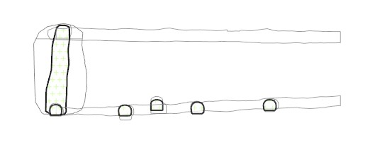
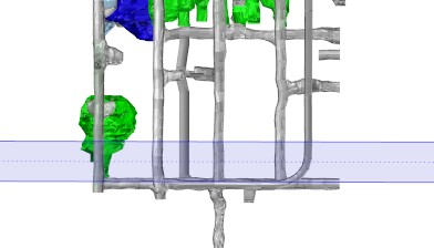
Draw Style: A new option, 2D Slice + Silhouette, has been added. This can be useful when you are viewing underground workings in section. The 2D Slice (dark border with light green hatch) shows the intersection with the screen plane, while the Silhouette (grey border, no fill) shows nearby workings or ore zones. When the 2D Slice cuts through an ore wireframe, the Silhouette give an appreciation of the maximum outer dimensions of the ore (within the section limits).
 |
 |
|---|
Be sure to try out these new Features of Micromine 2018 and If you need assistance or any additional information please don’t hesitate to Contact Support.
For more information about Micromine 2018 including it’s new features and improvements please visit our Micromine 2018 page.


